drawings

Building Sections

Hi! I’ve started a series of posts to help homeowners understand what their architect will provide in final drawings. If you haven’t already, please check here to understand what type of project you have, so that you can check through the drawing list. Since each project is different, its drawing set will look slightly different too… but the project type page is a good place to start.

So, without further ado…

Building sections

Building sections are one of my favorite things to draw. Imagine if you took a building, cut a vertical line right across and all the way through it, peeled off the back half, and peered inside.

The Nefelejcs Projekt by Merge Invisible

The Nefelejcs Projekt by Merge Invisible

It would look kind of like this, right? This is the Nefelejcs Projekt by Merge Invisible in Budapest, Hungary. It’s a thought-provoking urban art project, using data from the city archives and information from neighbors to recreate and mourn torn-down buildings in the 8th district. Save your old buildings and reuse them, folks.

Sorry, got distracted by art.

section.jpg

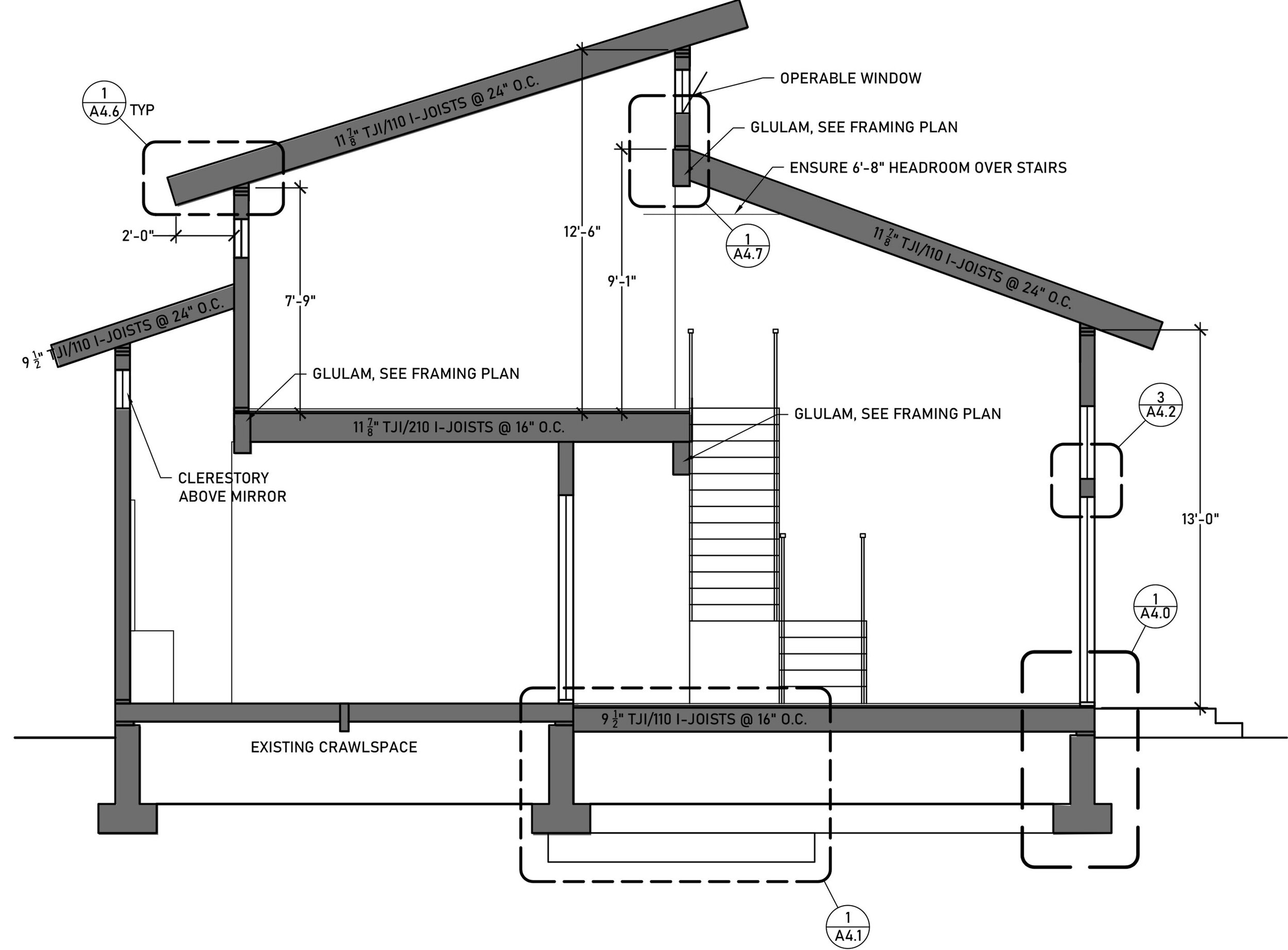
Building sections are incredibly useful tools for architects, engineers, and contractors. They help designers understand the constraints of a space. I use them a lot during design development to check stair clearances, joist depth, and ceiling heights. They’re important when coordinating various building components - if that overhead beam is 16” deep and a duct needs to run underneath it to get to the next room, what’s that going to do to our ceiling height??

Not only is a building section visually informative, but it’s also a road-map for construction details.

bubble.jpg

These bubbles pop up everywhere. They’re known as “callouts” and indicate that an area of construction is either atypical or very important to get right.  You’ll see them circling footings, structural connections, windows, and roof eaves. They’ll have two numbers indicated. The top is the drawing number, the bottom is the page number. So for the callout above, you’d check drawing 3 on page A4.11 to see a larger detail of that building assembly.

There you have it. Building sections. They might look like just another drawing, but in terms of understanding the constructability of a building, they’re the MVP.

Reflected Ceiling Plans

Hi! I’ve started a series of posts to help homeowners understand what their architect will provide in final drawings. If you haven’t already, please check here to understand what type of project you have, so that you can check through the drawing list. Since each project is different, its drawing set will look slightly different too… but the project type page is a good place to start.

So, without further ado…

Reflected Ceiling Plans!

RCPs are exactly what they sound like – looking at a view of the ceiling as if there were a mirror on the floor reflecting the ceiling back at you. It sounds complicated, but once you look at one, it’s actually pretty intuitive. It’s done this way so that the orientation of the floor plan and ceiling plan is the same. If you wanted to show the ceiling as if you were on the floor looking up, the plan would be reversed (and harder to read when compared to the floor plans). So. Reflected it is.

ceiling.jpg

And here’s what one looks like. We’re looking up at the ceiling for several reasons – special ceiling surface treatments, lighting, and life safety devices will be noted.  Reflected ceiling plans always come with a fairly extensive legend for fixtures, switches, and things like sprinklers or smoke detectors. Each fixture will have its own symbol and will be listed in the legend.

Proper lighting design is a huge deal. Well-distributed illumination is important in creating a visually comfortable room without glare or dark pockets. Many times, I’ll dimension the fixtures to let the contractor know exactly where lights should be placed in a room. Reflected ceiling plans should also show fixture switches so that they aren’t accidentally installed behind doors or in awkward corners.

Sometimes, my RCPs are combined with Electrical plans – if a homeowner wants to make certain that outlets are on either side of a bed for a bedside lamp plugin, for example, I’ll draw those in these plans as well. For the most part, though, we leave that to the electrician. They’ll abide by the International Residential Code, which has very clear instructions for where outlets should be placed and how far apart they should be.